Clayton Arnall
Investigations of the Compound Microscope
The compound microscope, in its simplest form is a system of two converging lenses used to look at very small objects at short distances. The lens closest to the object, called the Objective, is used to enlarge and invert the object into a 'real' image. The lens closest to the eye called the Eyepiece or Ocular acts essentially as a simple magnifier, used to view the image formed by the objective. The simple magnifier is a converging lens placed in front of the eye that increases the size of the image formed by the retina.
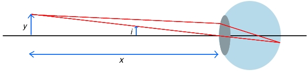
The angle i is given approximately by i = y/x

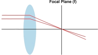
result is that rays emerge from the lens parallel, allowing the retina to focus
them at infinity. The new angle i' is given approximately by i' = y/f
The ratio i'/i is called the angular magnification, or M, the magnifying power of the lens.
- M = i'/i = x/f
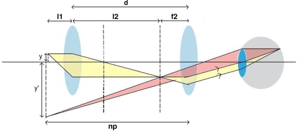
The eyepiece is placed such that the image formed by the objective falls at first focal point of the eyepiece. The light thus emerges as parallel rays.
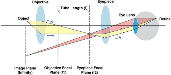
plane of the eyepiece (f2) is called the tube length (l). The object to be viewed is
placed just outside the focal point at the left side of the objective lens. The enlarged
image is formed at a distance l + f1 from the objective.
The eyepiece is placed such that the image formed by the objective falls at first focal point of the eyepiece. The light thus emerges as parallel rays.
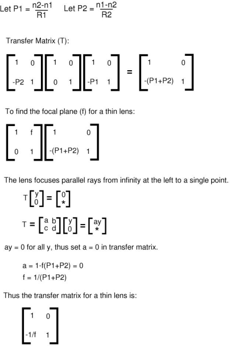
The system matrix of a compound microscope can provide more insight into the relationship between the lenses. As previously stated, the compound microscope is essentially a system of two thin lenses. Thus, we must begin by understanding the transfer matrix for a thin lens.
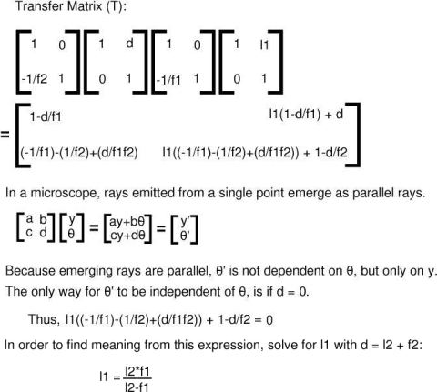
The system matrix of a compound microscope can be derived by combining transfer matrices from two thin lens systems in air using variables from figure 5 below.
given by (-l2/l1) * (np/f2), where np is the near point of the viewer (the nearest point
at which an average human eye can focus is 25cm).
The system matrix is as such:
EXAMPLE - If a microscope has an objective lens of focal length 1.2cm and an eyepiece of focal length 2cm separated by 20cm, the object should be placed at a distance l1 from the objective lens in order to be viewed at infinity(rays come into your eye parallel).
- l1 = l2f1/(l2-f1) = 21.6/16.8 = 1.29cm.
- M = -l2/l1 * np/f2 = 18/1.29 * 25/2 = -174.4
Limits of Resolution
To understand the limits of resolution in a microscopic system, we must examine briefly, light going through a slit comparable to the aperature of a microscope. Considering the wave nature of light, we can conclude that an object point does not give an accurate point on the image plane. The light is instead distributed radially around the ideal image point as demonstrated by figure 6 below.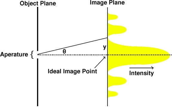
A circular patch of light surrounds the ideal image point. Around the patch are alternate dark and light rings given by the max and min of the intensite distribution. This effect is due to diffraction at the aperature and the spread of the diffraction pattern. As demonstrated by the distribution, the majority of the intensity of light is concentrated within a distance y from the ideal image point. The circular patch of light formed is known as the Airy Disk.
The resolving power of a microscope can be defined as the least distance y between two points in the object plain such that they are distinguishable from each other. This distance is related to the width of the aperature as the following equation demonstrates:

 is the numerical aperature of the sysem
The larger the numerical aperature, the smaller the distance necessary to distinguish two objects, and hence, the higher the resolving power of the instrument.
References
1. All images (expect figure 0) were created originally by us using Gimp in linux.2. Curry, C. Geometrical Optics, Edward Arnold & Co; London. (1953)
3. Tipler, Paul. Physics for Scientists and Engineers, Volume 2 Electricity Light and Magnetism 4th edition. W.H. Freeman & Co; Worth. (1990)
4. Malacara, Daniel, Geometrical and Instrumental Optics, Volume 25, Methods of Experimental Physics. Academic Press Inc; Boston. (1988)